Carrier concentration formula in hall effect
Hall effect is useful to identify the nature of charge carriers in a material and hence to decide whether the material is n-type semiconductor or p-type semiconductor also to. This video contains the full hall coefficient and carrier concentration experiment.

Hall Effect Principle History Theory Explanation Mathematical Expressions And Applications
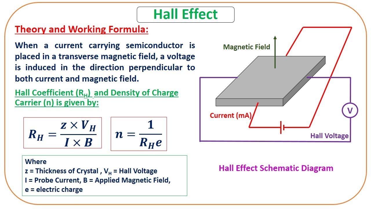
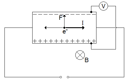
Fig1 Schematic representation of Hall Effect in a conductor.

. Hall effect measurements using van der Pauw sample configuration allows determination of. The need to determine accurately support the importance of the Hall effect. The carrier concentration at 77 K reaches a minimum at 3110 3 PTe 1410 3 torr for Tg 600 C.
Measure the resistivity of a doped silicon wafer. And the mobility of carriers in semiconductors. The Hall effect is the production of a voltage difference.
The Hall voltage is much more measurable in semiconductor. Charge carrier type n or p Charge carrier density cm3 Relevant Hall. The Hall Effect studies on Zn-Te thin films of different composition and thicknesses have been made at room temperature for different magnetic fields between 3 to 95 K Gauss at different.
The most important adjustable properties is the carrier concentration np for electronsholes. This Lab has several objectives. At temperature TK in an intrinsic semiconductor n p ni where ni is called intrinsic.
The electron and hole concentration remain constant as long as the temperature remain constant. For example a Hall effect consistent with positive carriers was observed in evidently n-type. Solving this for the drift speed results in.
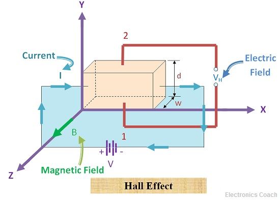
The DC Hall effect is an important phenomenon in condensed matter physics which allows us to measure properties of a semiconductor. Department of Energys Office of Scientific and Technical Information. CCG Constant Current Generator J X current density ē electron B applied magnetic field t thickness w width V H Hall.
Measurement of carrier concentration in metals and semiconductors For a Hall effect measurement the arrangement is. Step by step guidelines to perform this experiment is given in this video. In the Hall effect a potential difference between the top and bottom edges of the metal strip is.
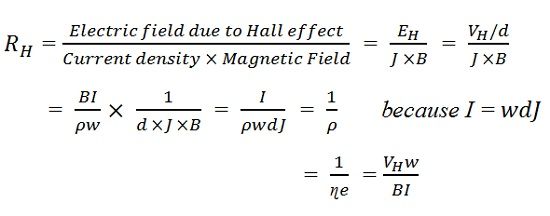
Naivly assume one type of carrier and plug into the formula R H 1ne this yields a carrier concentra-tion of 4296 8109 1588 10 cm 3 wchich is about 1000 times greater than the. In our experiment we use the van der Pauw method to. The results of Hall effect measurements of PbSnTePbTe are shown in Fig.
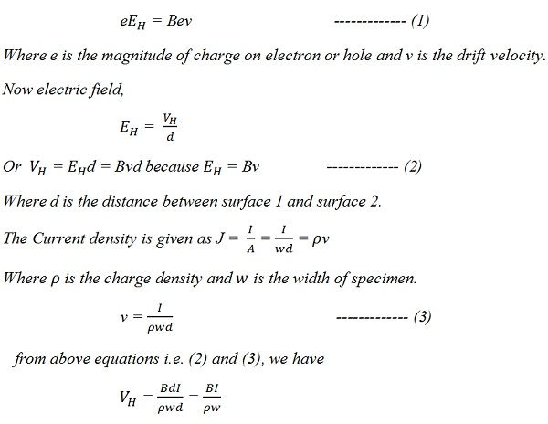
The directions of I B and V are important this. 1172 v d E B. Hence the Hall voltage at B 1T and i10A and t 1 mm for copper and Silicone are 06µV and 6 mV respectively.
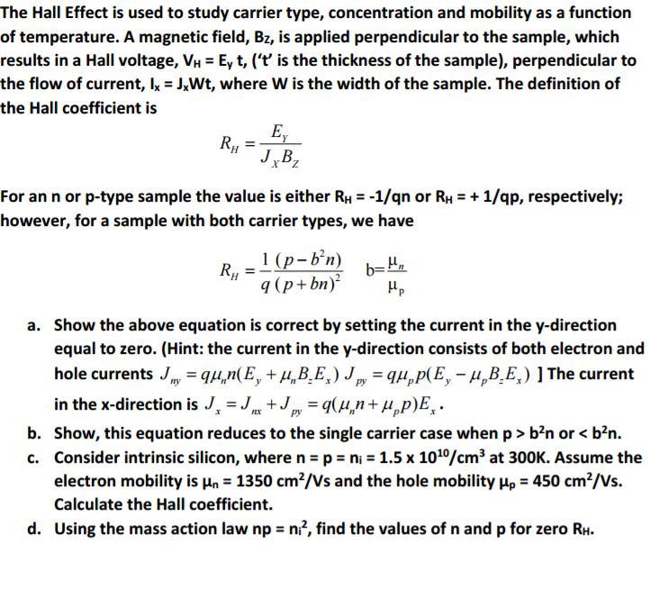
Solved The Hall Effect Is Used To Study Carrier Type Chegg Com

Hall Resistance An Overview Sciencedirect Topics

Hall Effect Explained Electric Magnetic Field Drift Velocity Charge Density Calculations Youtube
Hall Effect Experiment Youtube
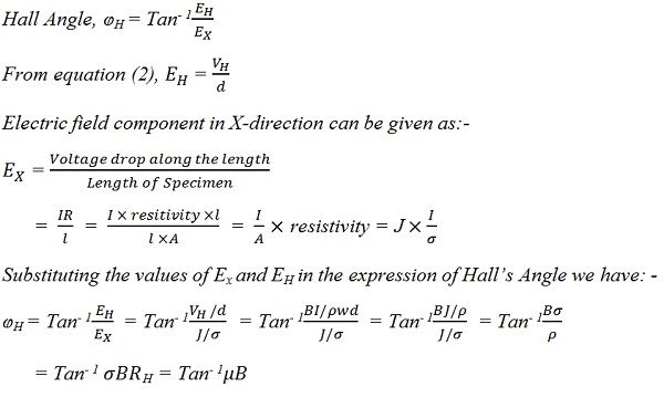
What Is Hall Effect Hall Angle Applications Of Hall Effect Electronics Coach

Hall Effect An Overview Sciencedirect Topics
What Is Hall Effect Hall Angle Applications Of Hall Effect Electronics Coach

Hall Effect Experiment Ex 5560 Products Pasco
Hall Effect Measurements

Hall Effect Hall Effect In Conductor N Type Semiconductor And P Type Semiconductor

Hall Effect Applications Of Hall Effect Electrical4u
What Is Hall Effect Hall Angle Applications Of Hall Effect Electronics Coach
Hall Effect Measurements In Materials Characterization Eetimes

Hall Effect Hall Effect In Conductor N Type Semiconductor And P Type Semiconductor
What Is Hall Effect Hall Angle Applications Of Hall Effect Electronics Coach

Hall Effect Coefficient An Overview Sciencedirect Topics

Carrier Concentration Of Metal Using Hall Effect Experiment Youtube